
Independent power supply with build-in power source,directly draws power from the incoming end to avoid the risk of protection function failure caused by external power supply failure.
● Overload protection
● Short circuit protection
● Isolation
● Controlling
● Used in residential building, non-residential building, industry, energy and infrastructure
● Small volume, convenient installation
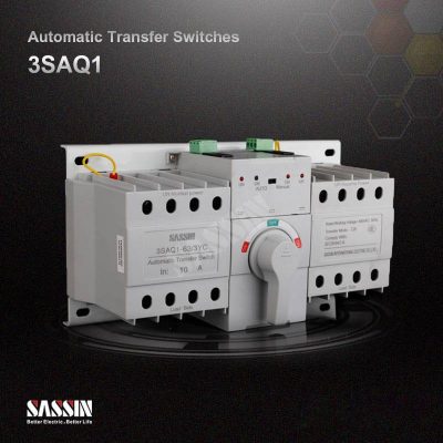
● With the controller, the setting can transfer between the manual and automatic transfer with restoration or automatic transfer without restoration
● Under-voltage, over-voltage, phase-loss protection
● Reliable and safe interlock, operation parameter could be adjusted
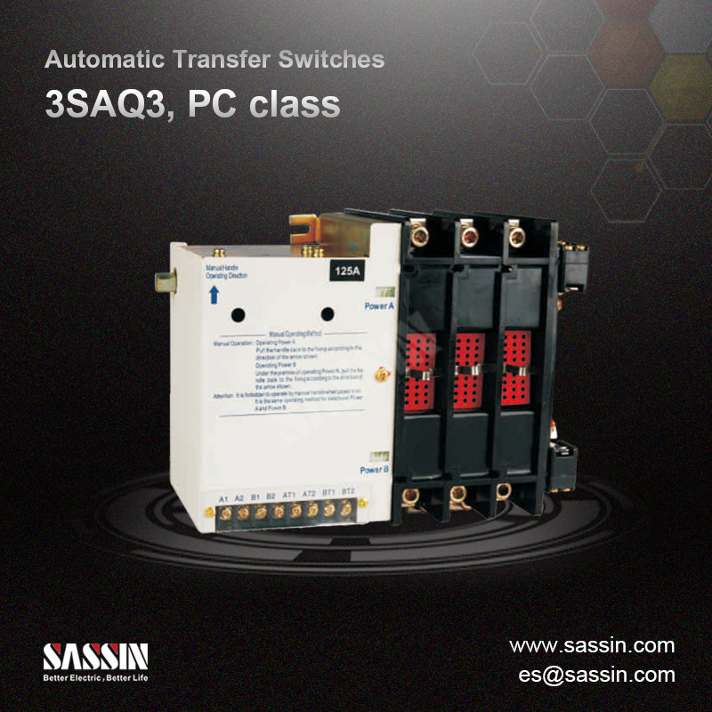
● Rated voltage of 400 V, rated current is from 20 A to 5000 A
● Low malfunction, easy maintenance
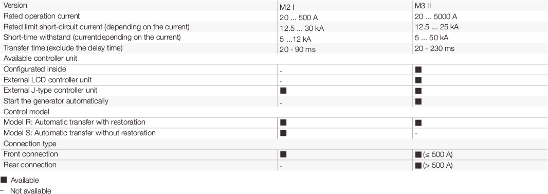
Versions
There are two available versions:
● M2 I: 2-stage, Power supply A ←→ Power supply B; M2 I automatic transfer switch is instantaneously switch type (without internal or external controller unit). If the switches are under maintenance or damaged condition where contineous power supply is required, it is possible to operate the handle by manual and identify the failure point by ovserving the switching actions
● M3 II: 3-stage, Power supply A ←→ Middle position Power supply B
M3 II automatic transfer switch has following functions
● Interchange of automatic between manual operation
● Voltage detection for three-phase four-line of power supply Aand B
● Over-voltage, under-voltage and phase-loss protection
● Automatic switching between power supply A and B
● Automatical fault handling
● Remote start/stop generator
● Over-current protection after connect; to an over-current relay via additional expansion interface
For both versions, if the automatic transfer switches are under maintenance or damaged condition while the contineous power supply is required, it is possible to operate the handle slowly by manual to identify the failure point by carefully ovserving the switching actions
Instruction of type code

Technical specificatious
Version M2 I

Technical specificatious
Version M3 II
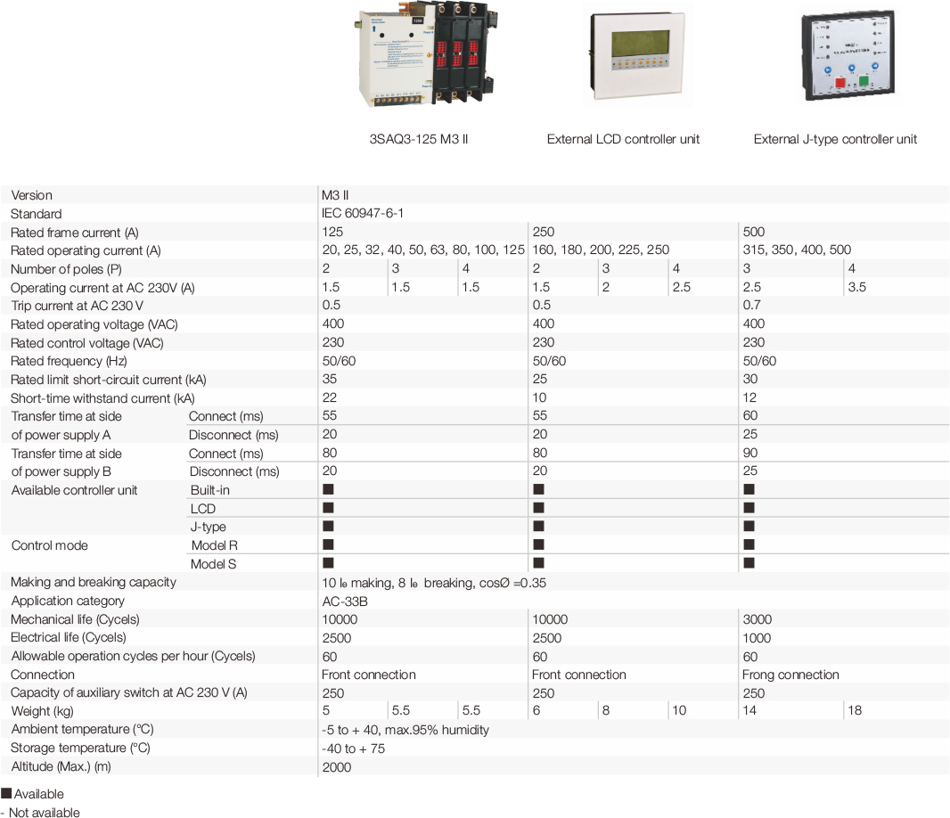
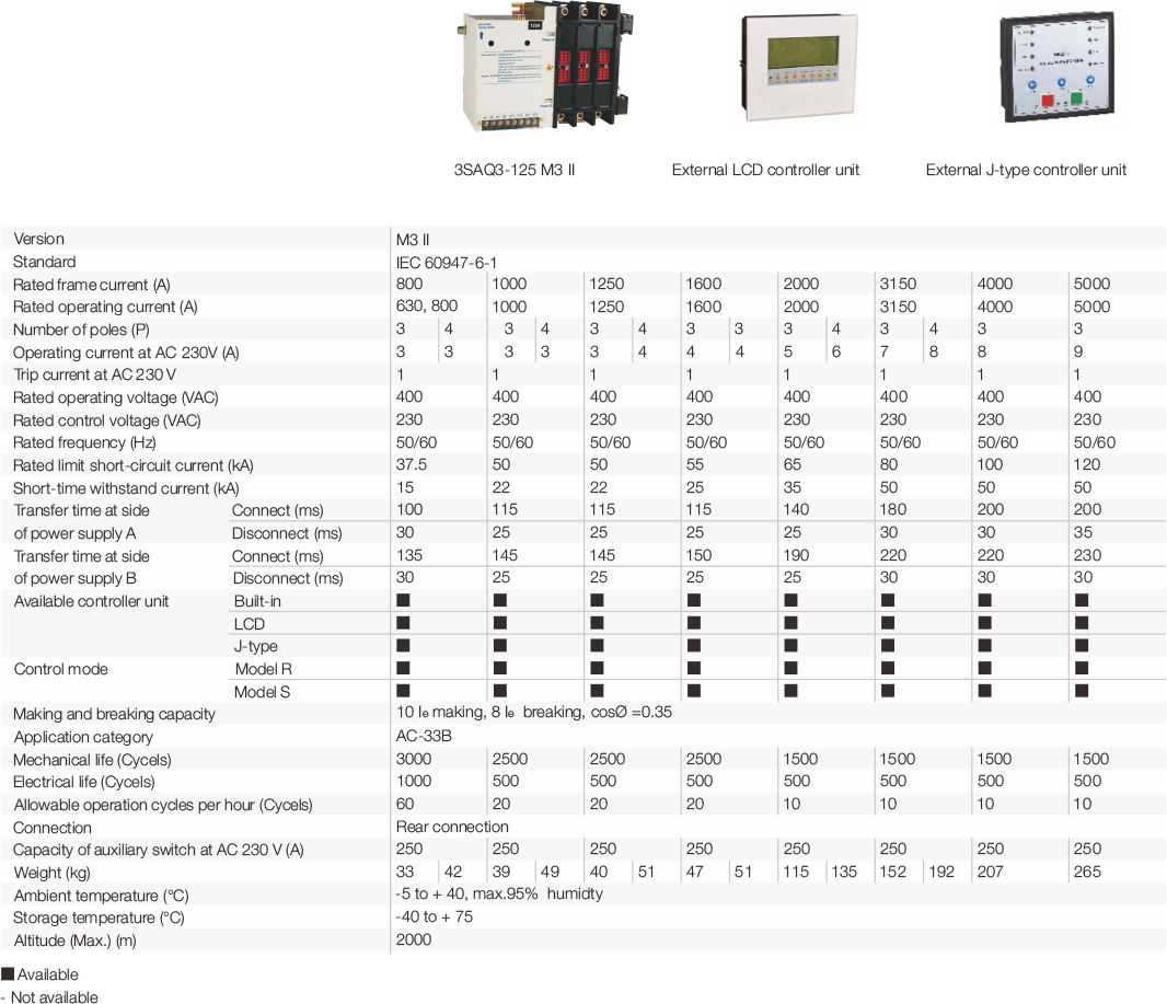
Technical specificatious
Version M3 II
External controller unit
There are two types available external controller units
● J-type external controller unit
J-type external controller unit is available for both versions of M2 I and M3 II

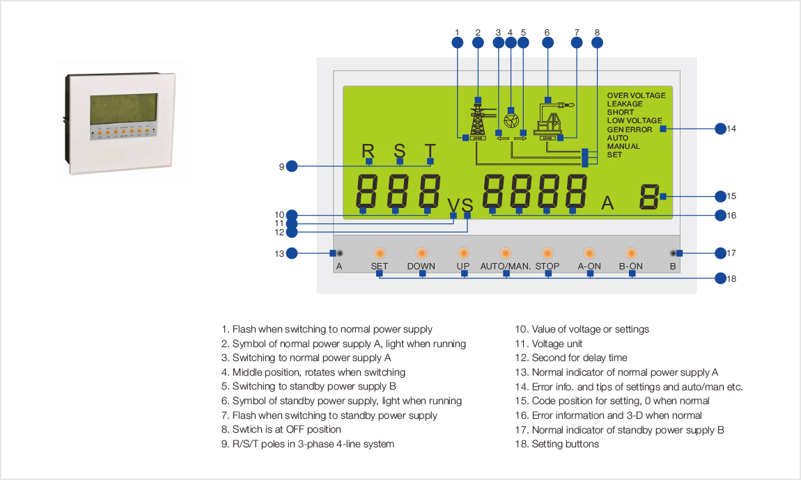
● External controller unit with LCD display
Wiring diagram
● M2 I version without controller unit
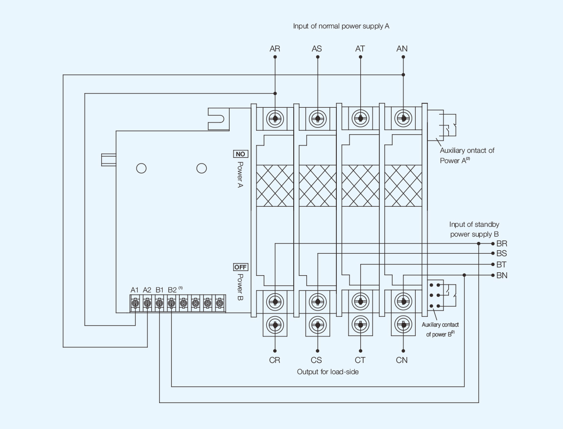
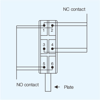
Auxiliary contact

Note:
1. A1/A2 is for input signal of power supply A, AC 220 V;
B1/B2 is for input signal of power supply B, AC 220 V;
2. Auxiliary contacts can be connected to indications, alarm or signals depending on needs.
Wiring diagram
● M2 I version with external J-type controller unit
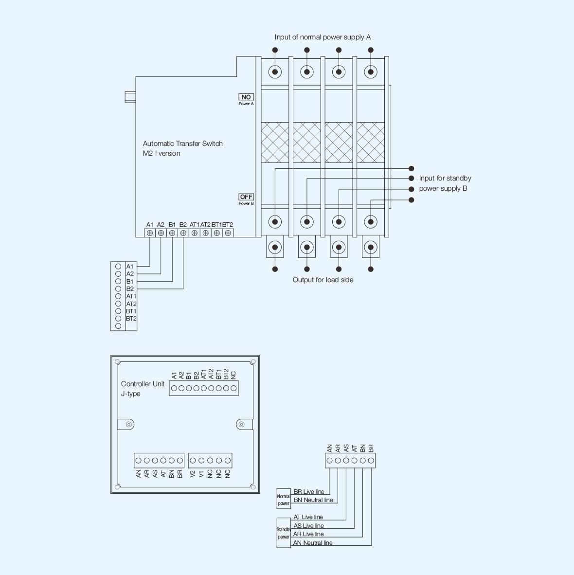
Wiring diagram
● M3 II version with internal controller unit
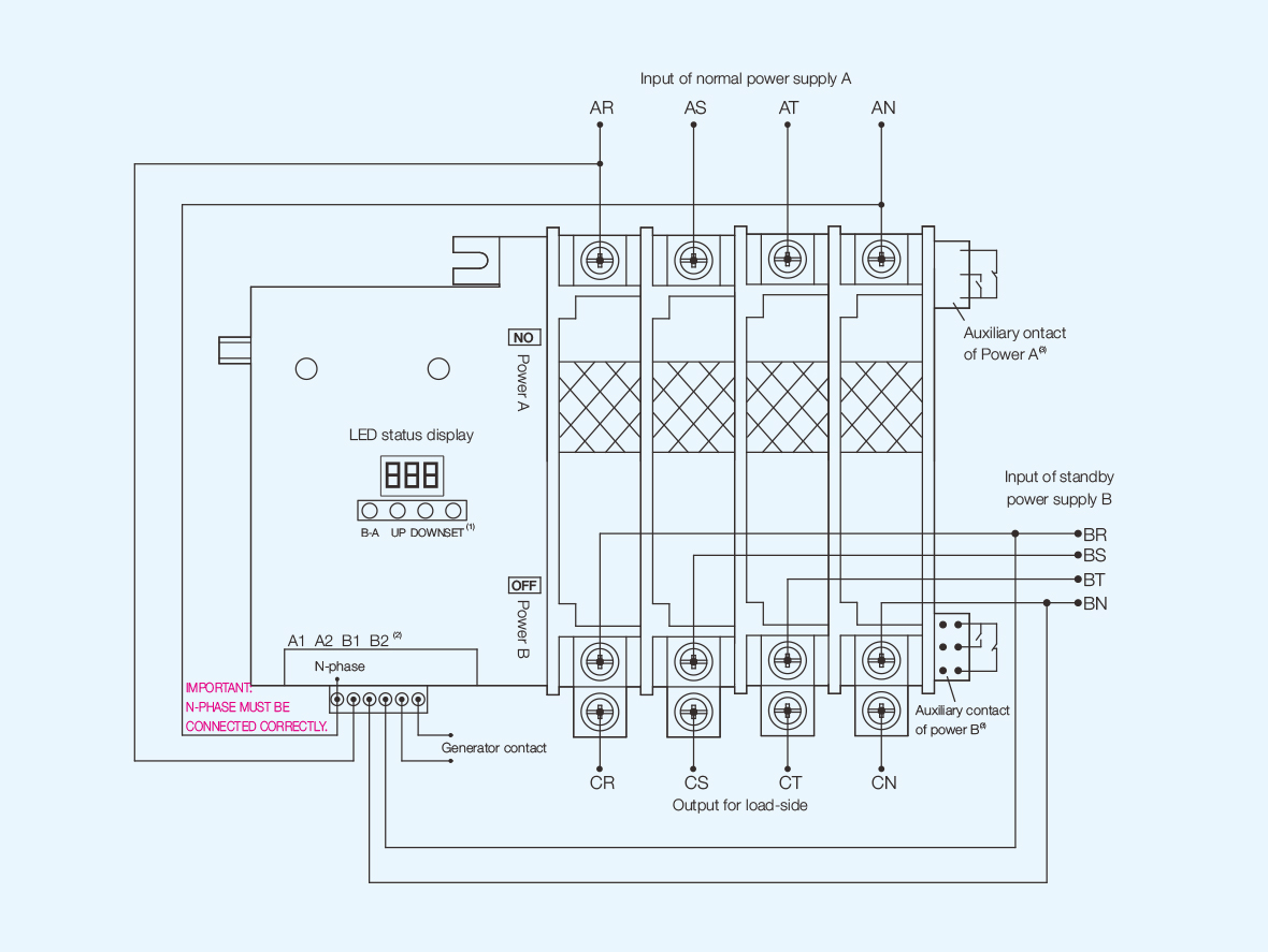
Auxiliary contact
Note:
1. Instruction of function buttons
Set: Settings for delay time of A-B, B-A or generator stop;
- Down: Reduction when setting;
Display B-phase voltage when automatical operating;
Switching to power supply B when manual operating;
- UP: Increase when setting;
Display A-phase voltage when automatical operating;
Switching to power supply A when manual operating;
- B-A: For exchange between Automatic operation and manual operation by pressing the buttons of SET and
B-A at the same time (manual operation is available when LED flashing);
- Setting the reference voltage of power supply A and B (LED display U-A and U-B)
2. A1/A2 is for input signal of power supply A, AC 220 V;
3. B1/B2 is for input signal of power supply B, AC 220 V;
Auxiliary contacts can be connected to indications, alarm or signals depending on needs.
Wiring diagram
● M3 II version with external J-type controller unit
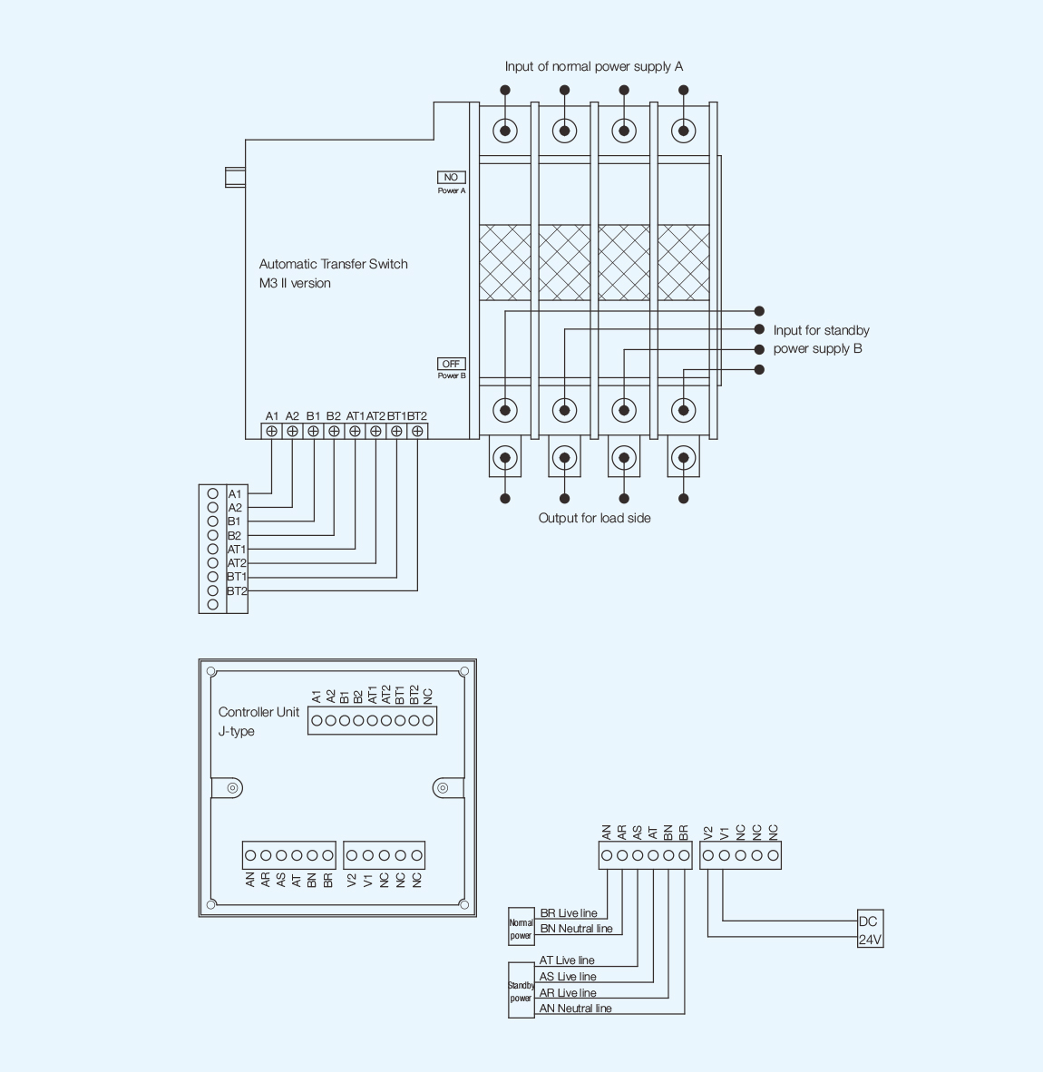
Wiring diagram
● M3 II version with external controller unit with LCD display

Auxiliary contact

Notice:
1. Instruction of function buttons
- SET: Settings for low and high voltage range of power supply A and B, delay time of OFF-A, OFF-B, B-OFF,
generator stop, problem of A and B, timing for generator starting; Codes are 1, 2, ... 9, C and D.
- DOWN / UP: Reduction (or incurease) when setting;
- AUTO/MAN: For exchange between Automatic operation and manual operation;
Setting the reference voltage of phase R/R/T for power supply A and B by pressing it for 3 seconds when
manual operation.
- STOP: Cut off from power supply A and B, switch to OFF position and entering standby;
- A-ON: Switch to power supply A at manual mode;
Display the voltage of phase R/S/T of power supply A at modes of automatic or stop;
- B-ON: Switch to power supply B at manual mode;
Display the voltage of phase R/S/T of power supply B at modes of automatic or stop;
2. Auxiliary contacts can be connected to indications, alarm or signals depending on needs.
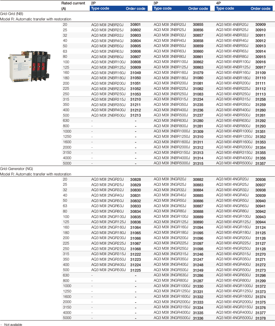
Selection and ordering data
M2 I versions without controller unit
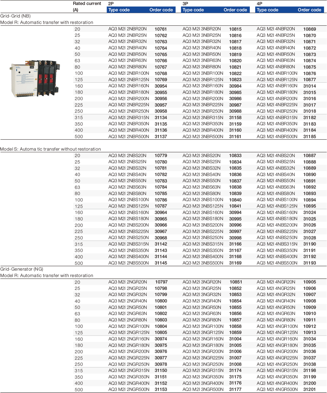
Selection and ordering data
M2 I versions equipped with external J-type controller unit

Selection and ordering data
M3 II versions equipped with internal controller unit
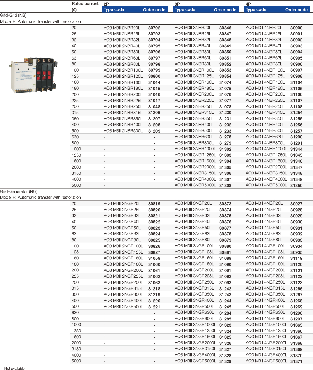
Selection and ordering data
M3 II versions equipped with external J-type controller unit
Selection and ordering data
M3 II versions equipped with external LCD display controller unit