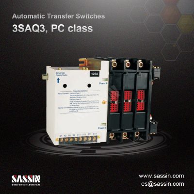


Independent power supply with build-in power source,directly draws power from the incoming end to avoid the risk of protection function failure caused by external power supply failure.
● Small size with simple structure
● Easy operation, long service life
● Both 3P and 4P are available
● Single electric drive, smooth and noise-free, small impact
● With mechanical interlock and electrical interlock, reliable switching, both manual and automatic switching are available
● Switch is wired with connection terminal in the internal for users, reflecting the circuit breaker status (open or closed)
● There are a variety of indicators listed on panel
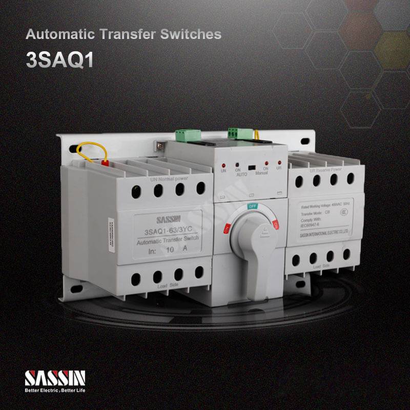
Structure and Performance
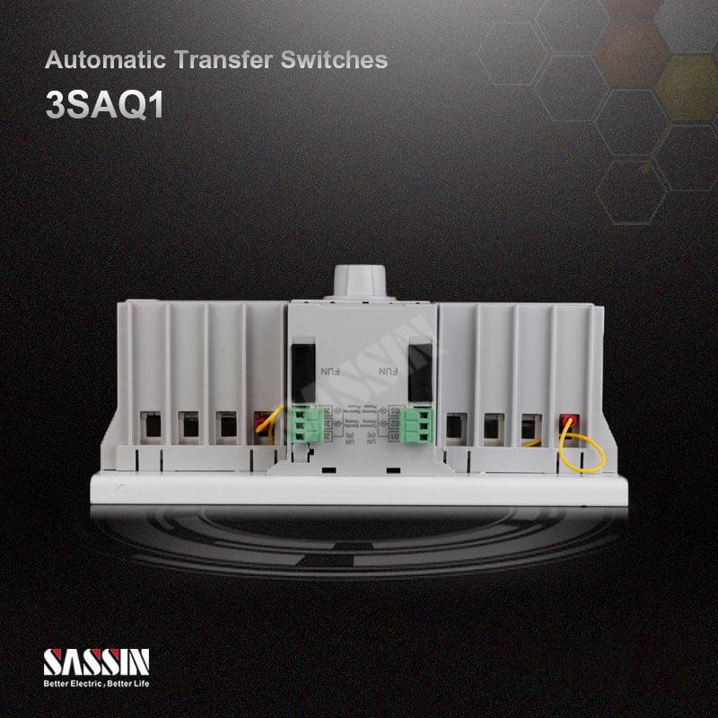
Structure
The automatic transfer switch consists of MCB, a single electric motor operating mechanism, mechanical interlocking, auxiliary systems, control circuit and other components and are closed with plastic shell. All components are installed on the same floor. There is a status indicator on the panel that accurately indicates the state of the MCB and the whole set of instructions.
Structure
● Automatic controllers (only R-type:automatic transfer with automatic restore) detect the voltage of two-way power (commonly used power and backup power) at the same time. Common power will work under the normal state. When the common power supply failure occurs, namely loss of pressure or A phase-off, the controller will automatically make the command switch switch to the backup power supply;
● When common power is restored to normal, the controller will automatically make the command switch switch to the backup power supply, and no delay;
● Simultaneous two-way power anomalies are not allowed;
● When tripping occurs due to a small circuit breaker failure, the device will remain in the trip state and let out a warning signal. Wait for maintenance, and the handle should be reset and re-closed manually after troubleshooting;
● In automatic mode, when there inputs DC 24 V fire signal, the controller will command all the disconnect switch,
and then if undo the fire signal, restore the original state.
Instruction of Type Code

● There is only R type for 3SAQ1 series ATS at present
● Automatic transfer with automatic restore: If deviation of common power is monitored , ATS will automatically
switch the load from the common power to backup power; if the power returns to normal, it will automatically return to common power supply
Technical Specifications
Wiring Diagram
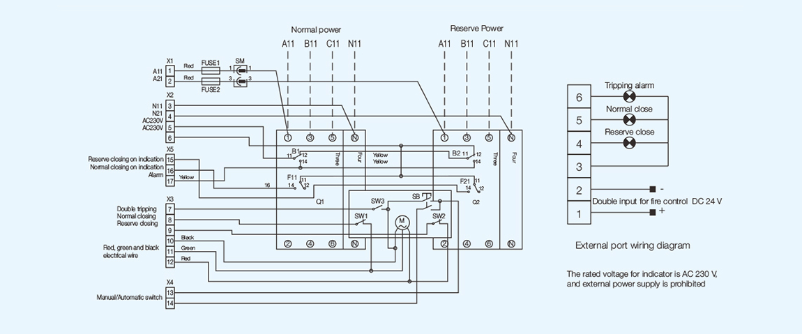
a) Q1, Q2: MCB (Double points for the location of the icon)
F21, B2: The right auxiliary and alarm head of circuit breaker
SW1: Common closing limit switch in place
SW3: Double points limit switch in place FUSE1, FUSE2: Fuses
SM: Three-pin connector
b) Dotted line is for the user to connect and the remaining for factory, for user's reference
F11, B1: The right auxiliary and alarm head of circuit breaker
M: Electric motor
SW2: Backup closing limit switch in place X1 X2 X3 X4 X5: Connectors
SB: Rocker Switch
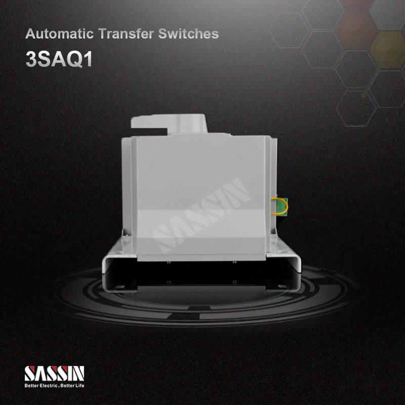
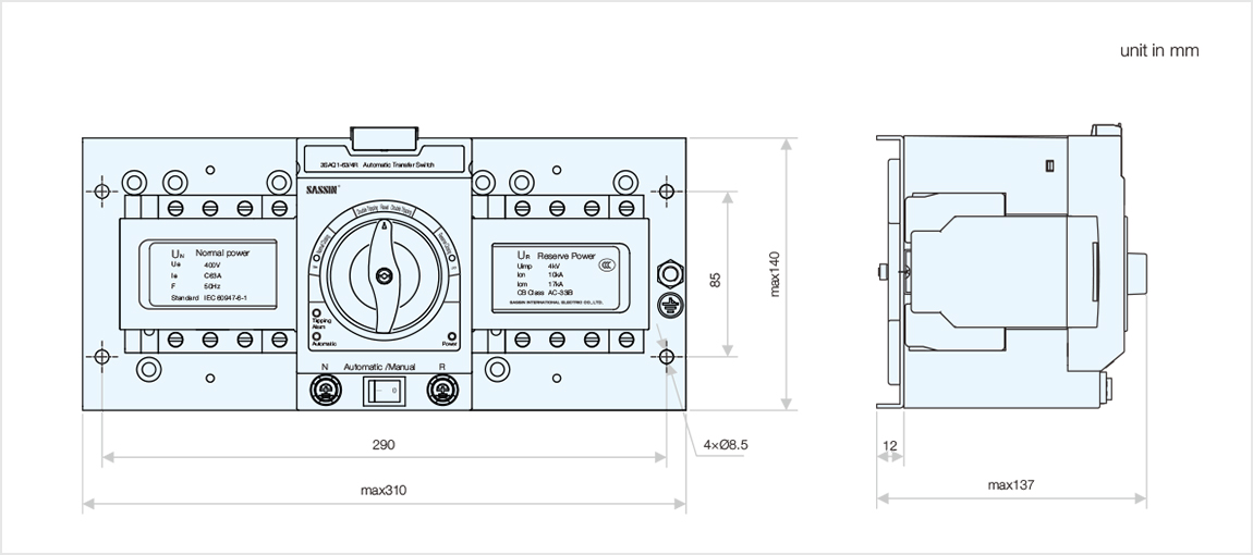
Outline and Installation Dimensions
Selection and Ordering Data

Utilization Categories
● AC-33iB: for system loads including cage motor and resistive loads
● AC-33B: for motor load or mixture load including motors, resistive load and 30% incandescent load
● Standard: IEC 60947-6-1