Independent power supply with build-in power source,directly draws power from the incoming end to avoid the risk of protection function failure caused by external power supply failure.
● Overload protection
● Short circuit protection
● Isolation
● Controlling
● Used in residential building, non-residential building, industry, energy and infrastructure
● Overload protection
● Short circuit protection
● Isolation
● Controlling
● Used in residential building, non-residential building, industry, energy and infrastructure
Technical specifications
● Standards: IEC 60898-1, IEC 60947-2
● Rated current In (A) : 2, 4, 6, 10, 16, 20, 25, 32, 40, 50, 63
● Rated voltage Un (V AC): 230/400
● Operational voltage (V AC): Min. 2; Max. 250/440
● Rated frequency (Hz): 50/60
● Rated insulation voltage (V AC): 500
● Number of poles: 1, 2, 3, 4
● Thermal operating limit (In): 1.13 - 1.45
● Rated switching capacity Icn (kA): 10
● Degree of protection: IP20, with connected conductors
● Electrical life (times): 10,000
● Mechanical life (times): 20,000
● Breaking capacity:
● Mounting position: Any
● Conductor cross-sections
● Solid and stranded (mm²): 0.75-35
● Finely stranded with end sleeve (mm²): 0.75-25
● Terminal tightening torque (N·m): 2.8
● Ambient temperature (°C): -25 ~ +45, max. 95 % humidity
● Storage temperature (°C): -40 ~ +75
● Altitude (meters): Max 2,000
References
● Additional components: page 189 ~ 191
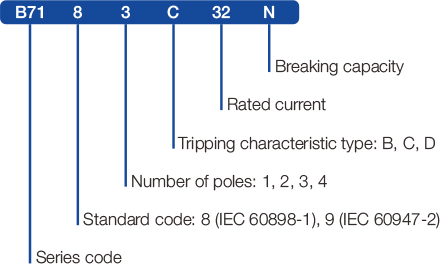
Instruction of type code
Features
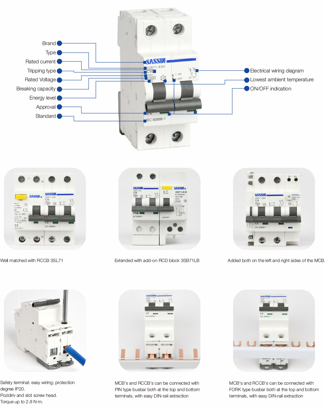
● The handle being sealable or equipped with padlock bracket avoids dangerous operation changes (ON / OFF)
● The handle provides a clear indication of the contact position
● Adequate printing of all data on the front provides long-term identification
● Energy limiting class: 3
● The emission of ionized gases is limited to the severest restrictions: 45 mm grid distance
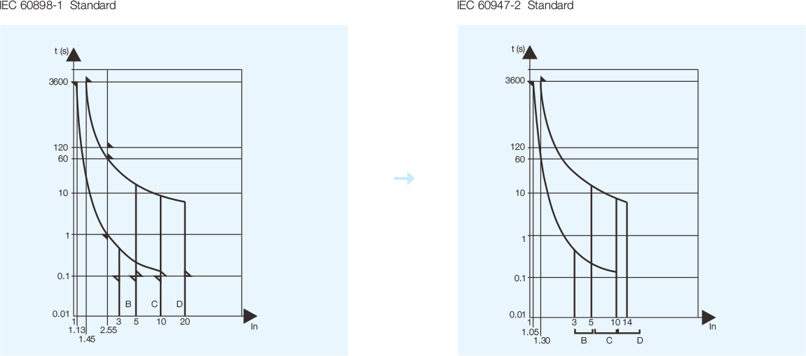
● This MCB for household in accordance with: IEC 60898 -1, B, C and D tripping characteristics
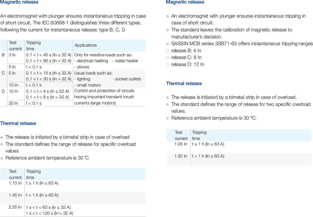
● This MCB for industry in accordance with IEC 60947-2 instantaneous tripping characteristics with release B: 4 In, release C: 8 In, release D: 12 In
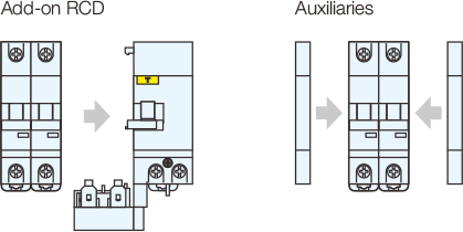
● This MCB may be extended with:
● A wide range of RCDs
● Full sets of accessories
Add-on devices
Benefits
● Attractive device design
● Easily recognizable, color-coded switching position
● Indication integrated in the handle
Selection and ordering data
IEC 60898-1 16 kA
IEC 60947-2 15 kA
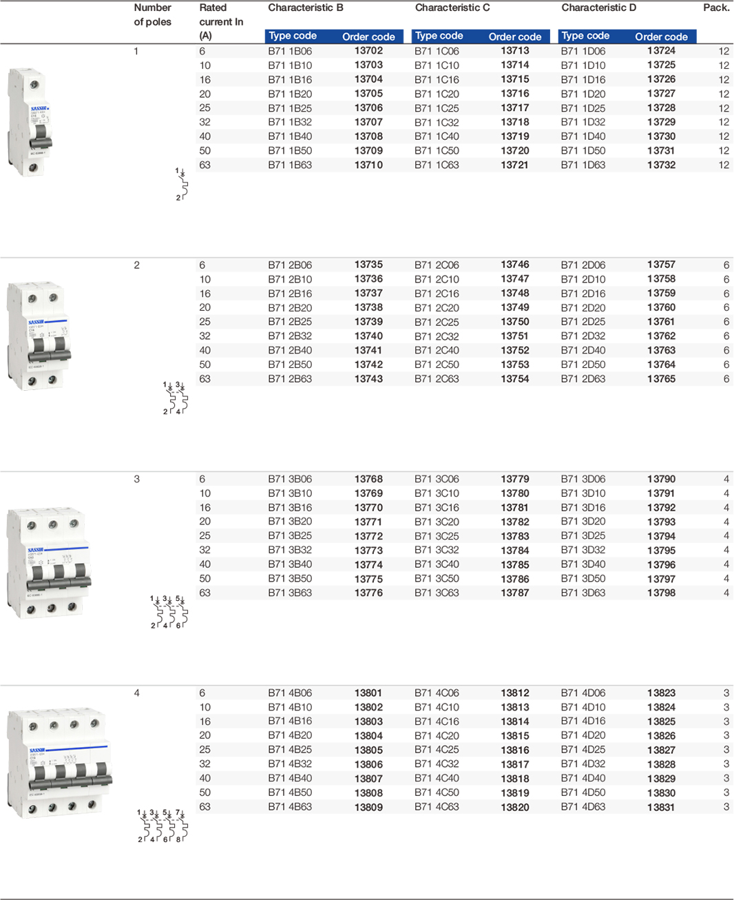
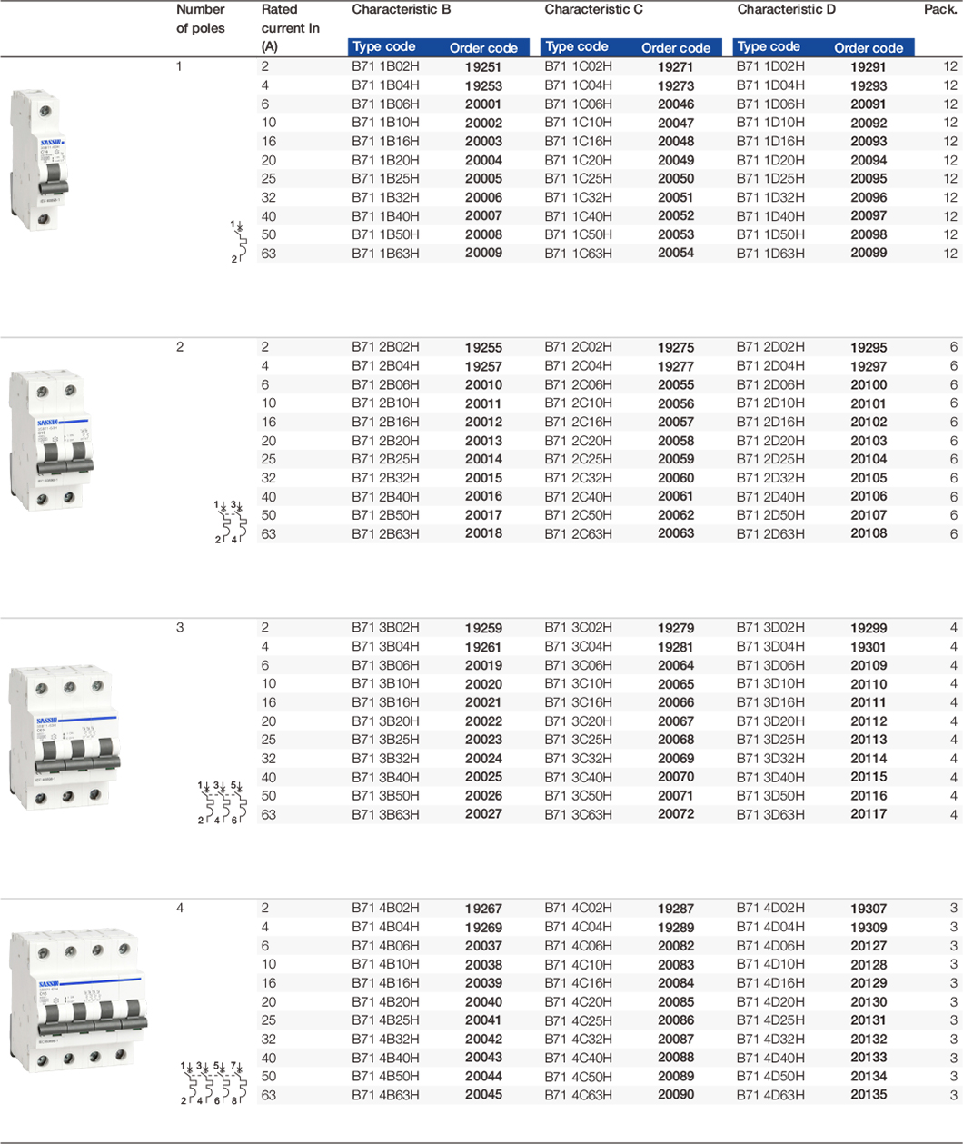
Selection and ordering data
IEC 60898-1 10 kA
IEC 60947-2 10 kA
Tripping characteristic curves
Selectivity
Load side: 3SB71-63,Characteristic B, C
Load side: 3SB71-63,Characteristic B, C
Back up protection
Load side: 3SB71-63,Characteristic B, C
Load side: 3SB71-63,Characteristic B, C
Temperature derating
The maximum permissible current in a circuit breaker depends on the ambient temperature where the circuit breaker is placed.
Ambient temperature is the temperature inside the enclosure or switchboard in which the circuit breakers are installed.
The reference temperature is 30 ºC
When several simultaneously operating circuit breakers are mounted side by side in a small enclosure, the temperature rise inside the enclosure causes a reduction in current rating. you must then assign the rating (already derated if necessary according to ambient temperature) a downrating factor of 0.8.
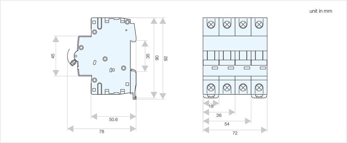
Outline and installation dimensions
